Aluminium strength that grows at cryogenic temperatures
Strength and ductility that increase down to −196 °C for cryogenic propellant tanks and LNG/LH₂ storage: a weldable, high-strength alloy for lighter tank structures with fewer compromises.
Description
Cryogenic storage and transport push materials to the extreme: ultra-low temperatures down to −196 °C and below, repeated thermal and pressure cycling, dynamic transport loads and demanding weld quality on large tank hardware. CrossAlloy.57 becomes stronger and more ductile as it gets colder, enabling lighter, weld-friendly tank structures.
Cryogenic strength has been tested on lab-scale material only; tensile and fatigue data on industrially produced material is still to be generated.
The CrossAlloy.57 advantage
- High strength at low temperatures : Thinner tank structures, reinforcement features and load-bearing components while maintaining robustness.
- Improved fatigue resistance : Supports dynamic load cycles and vibration over extended life cycles.
- Good joining and weldability : Weld-friendly structures that reduce manufacturing risk, rework and defect sensitivity in large tank hardware.
- Weight reduction with system impact : Lower tank mass improves payload capacity, transport efficiency and overall system performance.
Chemical Composition
The performance rests on the crossover chemistry: a high-magnesium 5xxx base made age-hardenable, hardening via the T-phase instead of the η-phase. Current internal specification limits and typical measured values are shown below.
| wt-% | Si | Fe | Cu | Mn | Mg | Zn | Cr | Ti | Zr |
|---|---|---|---|---|---|---|---|---|---|
| Min | – | – | 0.40 | 0.20 | 4.30 | 3.20 | – | – | – |
| Max | 0.40 | 0.40 | 0.70 | 0.45 | 4.90 | 3.60 | 0.20 | 0.15 | 0.10 |
| Typical | 0.15 | 0.21 | 0.50 | 0.32 | 4.65 | 3.43 | 0.06 | 0.02 | < 0.01 |
Remainder Al; other elements ≤ 0.10 each / ≤ 0.20 total.
Mechanical Behavior
Specific strength drives lighter tank structures and thinner walls. CrossAlloy.57 reaches Rp0.2 values up to 480 MPa (T6): well above the established cryogenic tank alloys 5083 (~215 MPa) and 6061-T6 (~276 MPa), above cryo-heritage 2219-T87 (~350 MPa), and below lithium-bearing 2195 (~560+ MPa) – all without lithium and with markedly better formability and weldability.
For HFQ/SPF processed parts the service behavior can be tuned within the provided range by modification of processing and heat-treatment parameters to accommodate a use-case-specific performance profile.
Typical values are shown below; establishing customer specifications is feasible upon request.
Strip / sheet 1.0 – < 6.0 mm
| Property | T4-FH1) | after HFQ/SPF | T6 | T76 | T73 |
|---|---|---|---|---|---|
| Rp0.2 (MPa) | 260–310 | 255–400 | 450–480 | 380–410 | 310–340 |
| Rm (MPa) | 430–470 | 440–500 | 510–540 | 470–500 | 430–460 |
| A (%) | 18–23 | 11–18 | 9–12 | 10–13 | 11–14 |
1) FH: Pre-treated after solutionizing and quenching to ensure optimal grain structure, limited natural aging and fast hardening during subsequent aging
Plate 6.0 – 75.0 mm
| Property | T451 | T6151 | T651 | T7651 | T7351 |
|---|---|---|---|---|---|
| Rp0.2 (MPa) | 270–300 | 370–390 | 440–470 | 370–400 | 300–330 |
| Rm (MPa) | 440–470 | 470–490 | 510–540 | 470–500 | 430–460 |
| A (%) | 20–25 | 12–16 | 8–12 | 9–13 | 11–14 |
Reference alloys in the field for comparison:
| Property | 5083 (O/H111) | 6061 (T6) | 2219 (T87) | 2195 (T8) |
|---|---|---|---|---|
| Rp0.2 min (MPa) | 115–125 | 240 | 352 | 538 |
| Rm min (MPa) | 270–275 | 290 | 434 | 565 |
| A min (%) | 12–16 | 6–10 | 5–6 | 6 |
Minimum values according to EN 485-2, aggregated over the thickness span shown for CrossAlloy.57, and MMPDS-2025 (Design values, A-/S-basis, longitudinal).
Bendability
Formed sheet parts such as tank hulls and tank domes need tight, crack-free bends. T4-FH bends readily but requires subsequent heat treatment to establish preferential in-use conditions; peak-aged T6/T651 needs a larger radius.
EN ISO 7438: Minimum bending radius to reach 90° without cracking, axis in rolling direction
| Thickness t | CA57 (T4-FH) | CA57 (T6) | CA57 (T451) | CA57 (T651) | 5083 (O/H111) | 5083 (H116) | 6061 (T6) |
|---|---|---|---|---|---|---|---|
| 0.5–1.5 mm | 1.5 t | 2.0 t | – | – | 1.0 t | – | 2.5 t |
| 1.5–3.0 mm | 2.5 t | 3.0 t | – | – | 1.0 t | 2.0 t | 3.5 t |
| 3.0–6.0 mm | – | – | 2.0 t | 3.0 t | 1.5 t | 2.5 t | 4.0 t |
Reference values according to EN 485-2 (minimum bending radius for 90° bending, informative).
Fracture Toughness
Tank hardware has to tolerate flaws from welding and handling without fast fracture under pressure and thermal cycling. The naturally aged T451 is the toughest condition and peak-aged T651 the least; the overaged T7651 sits between the two, and a batch composition optimized for toughness lifts it further. The values below were determined at room temperature.
ASTM E399: Plane-strain fracture toughness, compact-tension (CT) geometry
| Material | KIc T-L (MPa√m) | KIc L-T (MPa√m) | Rm (MPa) |
|---|---|---|---|
| CrossAlloy.57-T451 | 34–38 | 39–43 | ~430 |
| CrossAlloy.57-T651 | 18–22 | 25–30 | ~520 |
| CrossAlloy.57-T7651 | 21–25 | 27–33 | ~500 |
| CrossAlloy.57-T76511) | 28–30 | 39–41 | ~500 |
| 7075-T6512) | 24 (20–30) | 29 (22–33) | ~550 |
| 7075-T76512) | 25 (22–31) | 32 (24–47) | ~525 |
| 7075-T73512) | 30 (23–52) | 33 (27–40) | ~500 |
1) Batch composition optimized for high fracture toughness.
2) MMPDS-2025, Table 3.1.2.1.4 (plate): average of the reported data, min–max range in brackets.
Fatigue
Pressure cycling, transport vibration and years of thermal cycling make fatigue life a primary design driver. For cryogenic tank service the established field alloys are 5083 and 6061; standardized fatigue design curves suitable for a direct overlay are not available for these alloys. The aerospace handbook bands therefore serve as a conservative benchmark: CrossAlloy.57 tracks typical 7xxx aerospace alloys and clearly outperforms 2024.
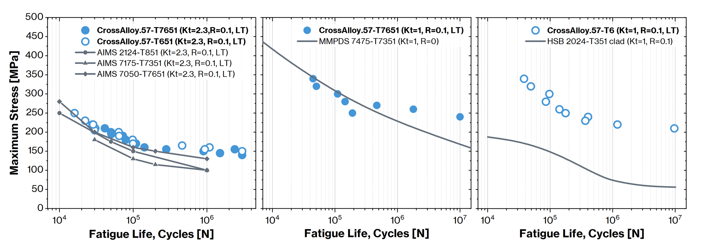
CrossAlloy.57 fatigue test points against aerospace reference data: notched (Kt=2.3) vs. AIMS 2124-T851, 7175-T7351 and 7050-T7651; unnotched (Kt=1) vs. MMPDS 7475-T7351 and HSB 2024-T351 clad.
Forming & Machining
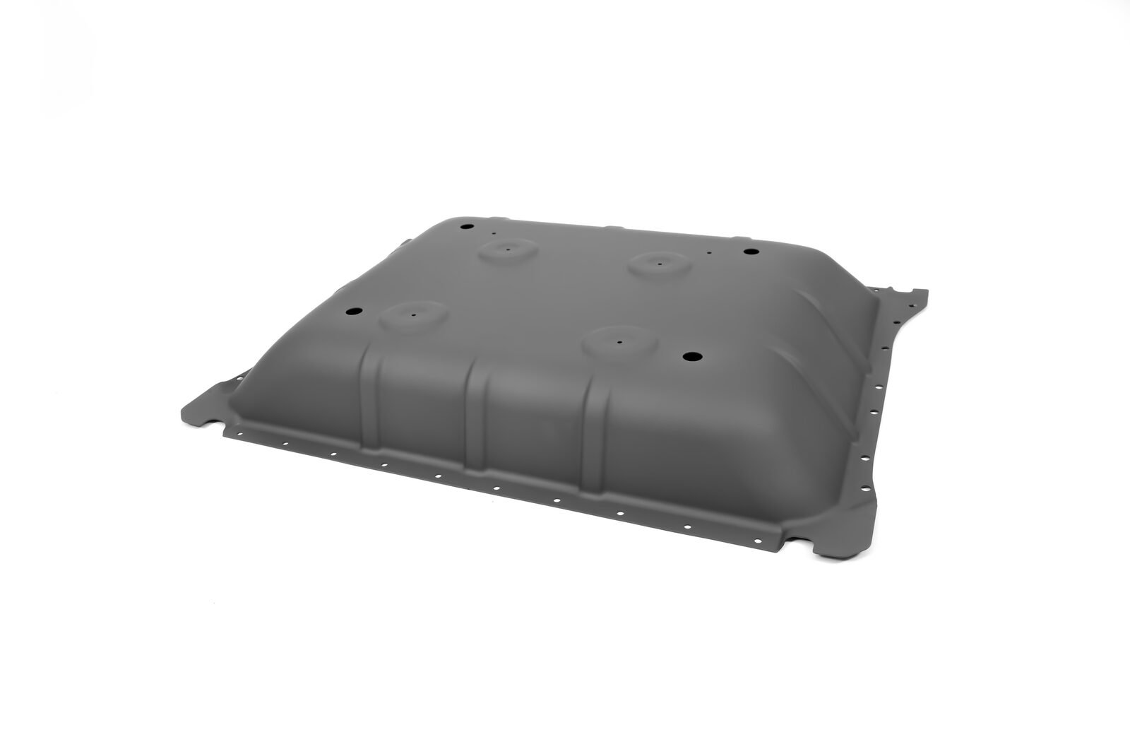
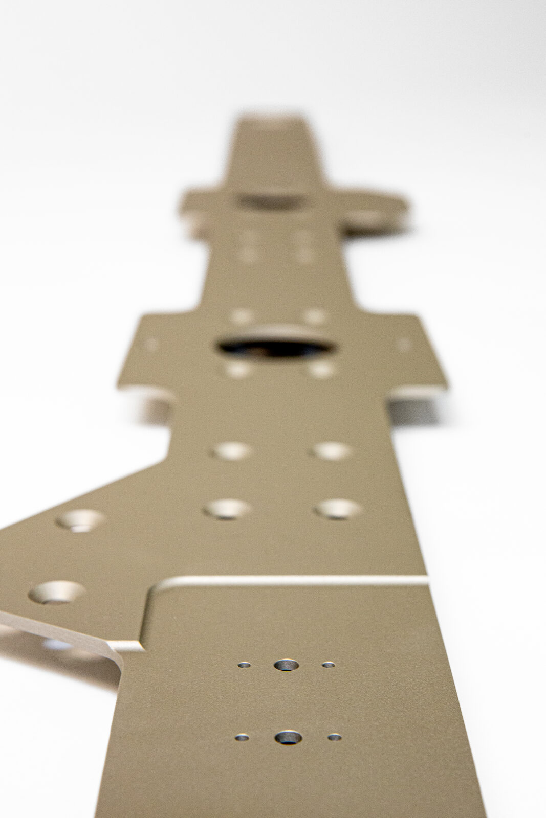
Cryogenic tanks combine formed and machined hardware: domes and hulls are formed from sheet and plate, while flanges, rings and interfaces are machined. CrossAlloy.57 machines with exceptionally low distortion due to minimal residual stress and without hot spots, enabling uniform in-service performance. The warm-forming routes (SPF for complex domes, HFQ for high-strength formed parts) complement cold forming of thin sheet. This lets tank domes and transitions be formed in one piece rather than assembled from many welded segments.
Corrosion
For tank hardware, stress-corrosion cracking (SCC) and media compatibility decide long-term integrity: LNG and LH₂ service adds moisture and condensation cycling on the outer surface. CrossAlloy.57 sits between the 5xxx and 7xxx alloys in SCC performance and is tunable by temper: the highly overaged/SCC-optimized condition T7351 reaches > 480 h, while peak-aged T651 is the SCC-weak point.
Similar to the mechanical behavior, corrosion resistance for HFQ/SPF formed components depends on the utilized processing and heat-treatment parameters.
| Condition | ASTM G67 (NAMLT) | ASTM G110 (IGC acc. 2xxx/7xxx) | ASTM G44/G47 (SCC) |
|---|---|---|---|
| T451 / T4-FH1) | < 5 mg/cm³ | < 100 µm | – |
| T6151 | < 10 mg/cm³ | < 100 µm | NA |
| T651 / T61) | < 20 mg/cm³ | < 100 µm | < 100 h |
| T7651 / T761) | < 30 mg/cm³ | < 100 µm | NA |
| T7351 / T731) | < 15 mg/cm³ | < 100 µm | > 480 h |
NA = not yet available; the required test duration has not been reached. Detailed SCC investigations are ongoing.
1) Conditions without cold work (T4-FH, T6, T76, T73) not separately evaluated; similar performance expected based on historical data for standard alloys.
Mechanical Performance at Cryogenic Temperature
Aluminium does well in the cold, and CrossAlloy.57 follows the physically expected trend: at −196 °C both strength and ductility increase. The chart shows laboratory tensile curves of CrossAlloy.57 (T4-FH, lab variant) vs. 5182 (O) at room temperature and in liquid nitrogen.
| CrossAlloy.57 (lab) | RT (25 °C) | LN₂ (−196 °C) |
|---|---|---|
| Rm (MPa) | ~394 | ~528 |
| A (%) | ~18 | ~33 |
Laboratory values on a non-industrial crossover variant, indicative only. Confirmation on industrial material at cryogenic temperature is still pending.
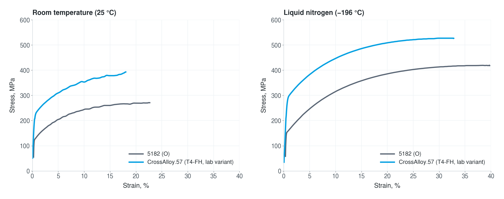
Laboratory tensile curves at room temperature and in liquid nitrogen: CrossAlloy.57 (T4-FH, lab variant) vs. 5182 (O).
Joining
Cryogenic tanks are large welded assemblies with long seams at hulls, domes and transitions, so weld efficiency and defect tolerance decide the design. CrossAlloy.57 is compatible with friction stir welding and behaves much like 5xxx alloys for arc welding; GMAW/GTAW were tested on 6/10/25/38.1 mm with no hot cracking. Weld-performance figures are indicative and require validation for specific use cases; joining tests at cryogenic temperature are not yet done.
| Process | Result (T651) | Note |
|---|---|---|
| FSW | > 75 % Rm retained | joint vs. base material, confirmed on 2, 3 and 6 mm |
| GMAW/GTAW | > 65 % Rm; up to 85 % Rm | 85 % with matching filler wire + post-weld heat treatment |
Physical Properties
| Property | min–max | mean |
|---|---|---|
| Density ρ (g/cm³) | 2.71–2.72 | 2.71 |
| Young's modulus E (GPa) | 70.3–73.0 | 71.7 |
| Shear modulus G (GPa) | 26.3–27.5 | 26.6 |
Potential use cases for CrossAlloy.57
Proposed applications are indicative and derived from cross-correlation between available material data and market research. They reflect where CrossAlloy.57 could add value from our perspective; given the limited information available to us, actual suitability is application-specific and is confirmed in cooperation with partners.
Cryogenic propellant tanks for space
Lightweight metallic tank structures for launch vehicles, upper stages and in-space propulsion requiring high strength, weld quality and mass efficiency.
Mobile cryogenic storage tanks
Tank components for LNG carriers, road tankers and vehicle-integrated LH₂ systems exposed to vibration, sloshing, pressure cycles and transport loads.
Land-based cryogenic storage tanks
Domes, transitions, nozzles, manways, supports and insulation interfaces for LNG and LH₂ storage under extreme temperature gradients.
Available Dimensions
| Thickness | Max. width (mm) | Max. length (mm) |
|---|---|---|
| 1.0–2.0 mm | ||
| T4-FH | 1650 | 4000 |
| T6 / T76 / T73 | 1500 | 6000 |
| 2.0–6.0 mm | ||
| T4-FH (up to 3.0 mm) | 2000 | 10000 |
| T6 / T76 / T73 | 1500 | 6000 |
| 6.0–12.0 mm | ||
| all Tx51 tempers | 1500 | 6000 |
| 12.0–150.0 mm | ||
| all Tx51 tempers | 1500 | 6500 |
Conservative assessment based on prototype production and limited number of lots. Additional dimensions available upon request.